Monday, December 6, 2010

Getting there - slowly

Grad school's been a bit more of a commitment than I originally anticipated, but I'm still finding some time to work on the bike.  Here's a rundown of everything I've accomplished on the main frame so far:

  • Mitered both ends of the top tube
  • Mitered both ends of the down tube
  • Ground out the down tube and seat tube sockets in the bottom bracket shell
  • Preliminary lug cleanup
I'm just about finished mitering the seat tube.  To finish the main triangle prep work, I still need to cut the seat tube to length and finish cleaning the lugs.  I also need to put a jig together.

Normally, you would simply slip the seat lug on to the seat tube at the appropriate length, braze the joint, and then cut the excess tube off.  My lug has an integrated collar for the seat post, which stops the lug from moving down the length of the seat tube.  So, I'll have to cut the tube to length before brazing.

Now that we've starting seeing consistently near-freezing temperatures during the day here, I'm concerned about brazing outside.  The temperature may be too cold for the joints to retain any heat while I'm trying to braze, but there's no ventilation in the basement and it would be a safety hazard to do the brazing down there.  I'm tempted to try to build a fire or light up the charcoal grill and try to get some ambient heat around my brazing space.

Tuesday, October 26, 2010

In Which Tools Are Aquired

I have purchased a Dremel.

In order to miter the other ends of the down tube and seat tube, it is first necessary to fit them into the bottom bracket shell in order to scribe the appropriate lines.  This has so far proven impossible, since the unfinished interior diameter of the BB sockets is a touch too small to allow the tubes to fully penetrate.

I have been diligently filing for several hours, but there are a couple of complications.  First, the filing needs to be done in a very cramped space - the main body of the BB shell prevents the file from traveling more than two or three inches (the length of the socket plus the diameter of the shell).  It effectively limits me to using the small needle files and course emery paper, neither of which removes much material; these are really meant more for finishing work.

Second, I have eczema on my dominant hand which makes work fairly painful after awhile.  I wear gloves when I can, but it limits my ability to work with emery paper (the fingers of the glove slide, or the paper slides against the glove), and the gloves end up binding in the BB sockets.  I generally lose the fine motor control and tactile feedback that you get from gloveless work.

So, the Dremel.  A grinding wheel attachment should fit nicely into the sockets and open them up enough to accept the tubing.  There is a risk using power tools here, and it's a reason I've avoided using them up to now - they remove material much faster than manual tools, which greatly increases the risk of taking too much metal off the sockets.  The most likely "bad" outcome would be taking the sockets out of round, but if the gap between the socket and the tube is too great then silver soldering will not be possible.  As always, going slow and steady will be paramount.

I may try using the Dremel on the tubing also, but I think the half-round file has been doing an excellent job so far.  Whenever I manage to install a real workbench in my shop space, I may also invest in a bench grinder.  The new tool should arrive in a few days.

Wednesday, October 13, 2010

Main Triangle Mitering - Part 1

Each tube in the main triangle must be cut to length and mitered before the frame is brazed together.  Before any cuts are made, I marked each tube with Dykem:


Each tube was marked roughly where the tubes needed to be cut to length, as well as the ends that would be mitered without cutting.  Keep in mind that the double-butted tubes have a short end and a long end; the tube is cut to length from the long end to maintain enough of a butt at each end of the tube.  The seat tube is single-butted, and is cut to length at the non-butted end.  The head tube is not butted and may be cut from either end.

First step - cut the head tube to length.  Make sure the tube ends up about 1/4" longer than your design to allow for facing.


There is no need to face the cut at this point, as it will be taken care of when the head tube is reamed after the frame is completed.  The rough cut on the head tube:


The next step is to miter the ends of the top tube and down tube that interface with the head tube.  To mark the tubes for mitering, I took the Dykem-painted ends, inserted them fully into their appropriate lugs, and scribed around the tube inside the lug.  There is also a piece of software available, tubemiter, that will allow you to print out the miter profile and tape the piece of paper to your tube.  The software may be more useful if you plan to bend your lugs or fillet braze/weld your frame.  Tracing the lugs was quick and simple, but was difficult to get a complete profile around the entire circumference of the tube.

Regardless of how you choose to mark your tubes, it is important to continually fit check your tubes.  An angle finder is useful during the mitering process to make sure the tubes are fitting at the correct angle.

Mitering is accomplished with a half-round bastard file.  Here is an image of the beginning of the cut on the top tube, with the scribed profile visible in the Dykem:


After a few minutes, the cut is deeper, but the "shoulders" of the miter are still squared:


Almost done, with rounded shoulders and just about reaching the scribed profile:


A close-up of the finished miter joint:


Fit-checking is accomplished by pressing the mitered profile against the head tube and peering through the joint at a light.  Any imperfections in the joint will be noticed by light leaking between the two tubes.  Making the miter profile meet the head tube as closely as possible will create a stronger joint.

Checking the top tube against the head tube:


Looking at the inside of the lug, with the mitered tube in place:


After the top tube is done, do the same thing to the end of the down tube that intersects the head tube.

The third miter profile to be cut is the seat-tube-end of the top tube.  Before cutting the profile, it is necessary to cut the top tube to length.  Be extra careful at this point, because there is no way to "undo" a cut that is too deep; if the tube is cut to too short a length, it must be replaced.

To mark the location of the cut, I installed the top tube and head tube in the top tube lug and then measured from the centerline of the head tube to the desired length of the top tube plus an extra 1/4"-1/2".  Essentially, I was looking to be able to fully insert the top tube into the seat tube lug in order to scribe the profile of the miter joint; cutting at the location described above may leave the top tube several millimeters too long, but this can be rectified with filing it down at the seat tube end.

After the top tube has been cut to length, scribe the miter profile as before.  To ensure the miter cuts are in the same plane, I kept the head tube in the top tube lug and aligned the seat tube lug using the workbench - the seat tube lug has flat sides which will line up with the head tube when the whole assembly is gently pressed against the (flat) work surface.

Carefully file the joint, making sure to stop occasionally and perform a fit check.  You can check for proper length by inserting the seat tube into the seat tube lug and measuring from the centerline of the seat tube to the centerline of the head tube.  My first cut ended up about 3 mm too long, which required scribing a second line and carefully (carefully!) removing extra material.

With these cuts complete, the next step is to consider the bottom bracket shell.

Friday, October 1, 2010

Parts List

Let's go over the parts necessary to build the frame.  Obviously, there are going to be more components than for the fork (which only had six pieces).

The lugs and the bottom bracket shell are what will hold the main triangle of the frame together:


Lugs are usually sold as a set - one price gets you a seat lug, top tube lug, and down tube lug.  These are matched for various seat tube and head tube angles.  I found what I needed at Ceeway; 72 degree head tube angles are not terribly popular and I couldn't find a US supplier.  Even with international shipping and exchange fees, the cost for the lug set came out to about $45.

Lugs can be manufactured in two ways - investment casting or stamping.  Casting involves pouring liquid metal into a mold, which is then broken open to reveal the finished product.  Stamped lugs are cut out of large sheets of metal, shaped, and then welded together.  Builders generally prefer cast over stamped lugs, as most believe them to be stronger.  Stamped lugs are cheaper, however, and more malleable.

If you are looking for a head or seat tube angle that is not generally available, lugs can be bent into the correct angle.  Cast lugs have about one degree of "give"; that is, you could bend a 73 degree head tube lug into a 72 degree configuration.  Stamped lugs can be pushed a little further and may be more desirable if you want to push them a little further.  For extreme lug angles, you may wish to consider making your own.  This can be accomplished by finding steel tubing with an inside diameter equal to the outside diameter of your frame tubing, with a wall thickness of about a millimeter.  Join two parts at the correct angle by mitering them properly and then MIG or TIG welding them together.  This can then be brazed during the frame build.

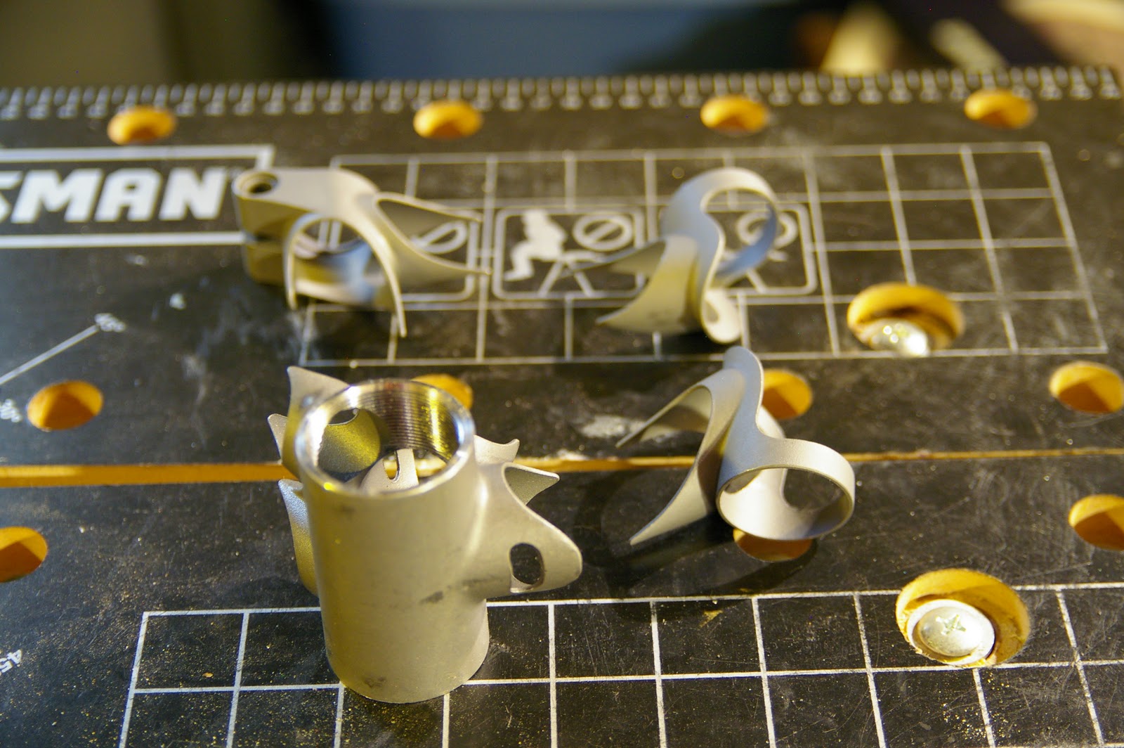
A view of the bottom bracket shell:


The shell has sockets for the seat tube, down tube, and chain stays.  Be sure to get a shell that matches the shape of the chain stays; if you have oval chain stays, you will need oval sockets on the BB shell.  This particular shell is already faced and threaded, and should be able to accept a bottom bracket with minimal extra work after the frame is put together.

In addition to the lugs and bottom bracket shell, you will need tubes.


A tube set will include one seat tube, one down tube, one top tube, a head tube, two chain stays, and two seat stays.  The dimensions of these tubes were covered in a previous post, but recall that the double-butted tubes have a short end and a long end; the end with the longer butt is usually marked.  These are marked with the part number of the tube.  Wall thicknesses are much thinner than for the fork blades, which will make it easier to shape them.

To accept a rear wheel, we need dropouts:


I decided to go with the socket style for the rear dropouts instead of the flat style to save time.  These are vertical dropouts; horizontal, or "track style" dropouts are also available.  This raises a question - why am I going with vertical dropouts instead of horizontal?  And why do my dropouts have a derailleur hanger?  Since I'm planning to go with an internal hub, the hanger is unnecessary and the drive train is essentially a "single speed" - one rear cog - so horizontal dropouts would make more sense.  In this case, vertical dropouts are somewhat more forgiving of manufacturing inaccuracies, which hopefully means that the bike will be rideable even if I screw up the rear triangle a little bit.

I was unable to find vertical dropouts that do not include a derailleur hanger, so I will either a) leave it as it is in case I want to swap out to a cassette later, or b) file it off.

To attach a brake and accessories, there are these small parts:


From top to bottom, I have a brake bridge, two rack mounts, and two eyelets.  The brake bridge is installed between the two seat stays, and not only provides a place to mount a rear brake but also adds some lateral support to the rear triangle.  The rack mounts look like small barbells and are brazed on to the rear dropouts.  The eyelets are also brazed on to the dropouts and can be used to mount either a rack or fenders.  I may not need both the eyelets and the barbells, but they were about 60 cents each so I bought them to have options.

Finally, I got these things:


These are seat stay caps.  They are brazed into the ends of the seat stays, and then attached to the main triangle.  Either the flat or concave side can face outwards, providing two different styles in one package.  These are not strictly necessary; Talbot describes a method of finishing the tops of the seat stays that involves taking some scrap metal and brazing it to the openings at the tops of the stays.  I may try this in the future, but for now I'm going to take the easy way out.

Missing from the parts list are all the braze-ons that will be needed to route cables, mount pumps and bottle holders, etc.  I've put off purchasing these for now until I get a better idea of what I want to go where.  Since they are all installed after the frame has been built, I have some time to think about it.

Thursday, September 9, 2010

Parts and Workload

My outside workload has increased significantly due to starting grad school (and working a full-time job...) so work on the bike may slow down a bit.  I will do my best to get this bike done - hopefully by the end of the year.

I have inventoried the parts I ordered for the frame, and I've noticed one major issue so far.  I bought the Nova Cycles standard "road" tubeset, but none of the tubes are marked.  One end of the tube usually has a longer butt than the other end - the long end is the one that should be cut to length - and the longer end is usually marked in some way.  These aren't, and it's very difficult to tell which end is which - the difference between the thick wall and the thin wall is only 0.3 mm!

A full description of all the parts with photos will be forthcoming.  Let's look at the tube set characteristics right now.

Tube sets are broken into two main categories: standard and oversize.  These categories define the outer diameter of the tubes; larger diameter tubes are stiffer and can withstand larger loads.  Heavier riders and mountain bikes tend to utilize oversize tubes, but any bike may use oversize tubing for the extra stiffness.

The standard size tube set includes a 25.4 mm (1 inch) top tube and 28.6 mm (about 1 1/8") down tube and seat tube.  The head tube is sized for the steerer tube that was previously chosen; I have a 1" steerer, so a 31.8 mm head tube will accommodate it.  The larger 1 1/8" steerer is paired with a 36 mm head tube.

Seat stays and chain stays can be purchased separately or may be included in the tube set, and there are a wide variety available.  Straight seat stays seem to be the most prevalent; "straight" in this case means that the tubing is of a constant, round diameter the entire length of the tube.  Chain stays are generally either "round-round" (RR), "round-oval-round" (ROR), or "oval-round" (OR).  Round-round describes a tube that has a round cross-section the entire length of the tube, but is a smaller diameter at one end than at the other.  Round-oval-round tubes start (from the larger end) as a round cross-section, gradually meld into an oval section mid-tube, and then return to a smaller-diameter round section at the dropout end.  Oval-rounds have an oval cross-section at the large end and a round section at the narrow end.

The differences in chain stay styles is, I believe, largely cosmetic, but there may be some minor performance differences between them.  The biggest difference to note at this point is that the style of chain stay must match the bottom bracket shell that has been purchased - some BB shells accept oval chain stays, and some accept round.  Always note which type of chain stays are required before purchasing the BB shell.

The tube set that I purchased include the following dimensions:


Dia. (mm) Wall (mm) Length (mm)
DT 28.6 0.8/0.5/0.8 650
TT 25.4 0.8/0.5/0.8 600
ST 28.6 0.9/0.6 650
CS 22 RR 0.8 420
SS 14 ST 0.8 560
HT 31.8 1.1 200

Notice that the down tube and top tube are both double-butted, and the seat tube is butted only at one end.  The notation "0.8/0.5/0.8" indicates that one end of the tube has a wall thickness of 0.8 mm, the tube tapers to a 0.5 mm thickness in the middle, and then expands again to 0.8 mm at the other end.  This can also be notated as "8/5/8".  Nova also requires specifying a head tube size when ordering, so I picked the one that is meant for a 1" steerer.

Monday, August 30, 2010

Fork Brazing and Finishing

The final steps to complete the fork are brazing the blades on to the fork crown and then cleaning up the mess.  After brazing, check the alignment of the fork with a trued wheel; if it wobbles, you must cold set the fork.  Cold setting is the process of mechanically adjusting the alignment of the fork blades, usually by carefully bending them into place with a cheater bar.

First, the tangs on the crown need to be cleaned up.  Casting leaves a slightly rough and pitted finish which must be removed, leaving behind a smooth face for the filler to bind to.

Clamping the steerer/crown assembly in place:


I started with the warding file, then worked the tangs with course grade emery paper.  The emery paper is used in an action similar to polishing the toe of a shoe:


I rolled up a piece of emery paper to clean up the inside of the tangs.  Not strictly necessary, I think, since there's nothing being joined inside of the tang.  Removing a little bit of material from the inside should help the joint to heat up quicker without risking deforming the tang:


While I was sanding down the tangs, I occasionally check fitted the fork blades to make sure I was not taking too much material off.  Once the tangs looked fairly smooth, I turned my attention back to the fork blades.

The blades need a small hole drilled in each of them to allow expanding gases to escape during the braze.  Without performing this step, the gases have nowhere to go except through the joint you're trying to make - this will leave cavities in the filler and potentially weaken the joint.  I positioned the hole on the inside of each blade, about two inches from the top of the blade.  The positioning of the hole is not terribly critical; my Raleigh has vent holes a couple of inches above the dropouts instead of near the top.  Make sure that the hole is further down the blades than the length of the fork crown tangs or lugs.

Marking the location of the holes with an automatic center punch:


I used a 3/32" bit for the holes:


After deburring the ends of the blades and removing the Dykem, this is what they look like:


Now is the time to jig up the fork.  Brush flux over the tangs and the inside of the blades, fit them together, and then secure everything in the jig.  I secured the dropouts on to the threaded rod first and then clamped the steerer securely to the block at the top of the jig.

While I was jigging the fork, before clamping the steerer tube, I noticed that the fork did not want to line up with the block that I had secured for the steerer.  Since I am fairly confident about the jig's correctness, I believe that one of the fork blades is likely ever so slightly short.  I forced the steerer against its clamping block, which left a small gap (maybe a millimeter or so) between the shoulder of the fork crown and the top of one of the fork blades.  Assuming the joint is secure, I don't think this is a safety issue - I can put some filler material in there to ensure the paint job looks clean.


The fork, fluxed and jigged:


I made sure to use metal C-clamps near the joint to avoid melting the plastic ratchet clamps.  After brazing, this is what the fork crown looks like:


And the entire fork, finally in one piece:


I let the fork cool in the jig until I could handle the steerer tube by hand; after that, I removed the clamps from the steerer and let it cool fully on the jig.  Once cool, the work is fairly routine - clean off the excess flux with a wire brush and water, file away the excess filler, and clean up the joints with emery cloth.

These joints are brazed with silver, but if your tolerances are very loose for some reason it may be necessary to use brass.

Now that the fork is completed (I'll have a photo of the finished product soon), it is time to start the frame.  I'm waiting on the Talbot book from the library, but in the meantime I can start cleaning up the lugs and cutting the head tube.

Monday, August 23, 2010

Back from Travel

I'm back from some R&R and business travel, and will post the final step of the fork build soon.  I managed to get the blades brazed on to the fork crown the day before I left, and all that's left to do is clean up the joints!  Parts for the frame have also arrived, and I'll start jigging that up as soon as I can make it down to the hardware store for some plywood.